Resource
BE1-11, Drawing: Front, J Case (PDF)
This drawing provides front-panel layout, dimensional details, display and control locations, and enclosure information for BE1-11 Series protection systems in a J Case enclosure.
Resource
BE1-11, Drawing: Front, J Case (DWG)
This drawing provides front-panel layout, dimensional details, display and control locations, and enclosure information for BE1-11 Series protection systems in a J Case enclosure.
Resource
BE1-11 (f,g,i,m,t), Drawing: Rear, RJ-45 Ethernet, J Case, 7 Inputs 8 Outputs (PDF)
This drawing provides rear-panel layout, terminal connection, and Ethernet port information for BE1-11f, BE1-11g, BE1-11i, BE1-11m, and BE1-11t protection systems in a J Case enclosure with RJ-45 Ethernet, 7 inputs, and 8 outputs.
Resource
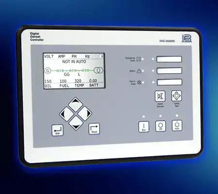
DGC-2020 Instruction Manual, Rev AB, English
This instruction manual provides information for the installation, setup, operation, maintenance, and troubleshooting of the DGC-2020 Digital Genset Controller, including graphical user interface operation, expansion module integration, communications, protective functions, and system configuration.
Resource
BE1-11 (f,g,i,m,t), Drawing: Rear, RJ-45 Ethernet, J Case, 7 Inputs 8 Outputs (DWG)
This drawing provides rear-panel layout, terminal connection, and Ethernet port information for BE1-11f, BE1-11g, BE1-11i, BE1-11m, and BE1-11t protection systems in a J Case enclosure with RJ-45 Ethernet, 7 inputs, and 8 outputs.
Resource
BE1-11 (f,g,i,m,t), Drawing: Rear, Fiber Optic Ethernet, J Case, 7 Inputs 8 Outputs (PDF)
This drawing provides rear-panel layout, terminal connection, and fiber-optic Ethernet port information for BE1-11f, BE1-11g, BE1-11i, BE1-11m, and BE1-11t protection systems in a J Case enclosure with fiber-optic Ethernet, 7 inputs, and 8 outputs.
Resource
BE1-11 (f,g,i,m,t), Drawing: Rear, Fiber Optic Ethernet, J Case, 7 Inputs 8 Outputs (DWG)
This drawing provides rear-panel layout, terminal connection, and fiber-optic Ethernet port information for BE1-11f, BE1-11g, BE1-11i, BE1-11m, and BE1-11t protection systems in a J Case enclosure with fiber-optic Ethernet, 7 inputs, and 8 outputs.
Resource
BE1-11, Drawing: Outline, H1 Rack-Mount Case (PDF)
This drawing provides outline dimensions, mounting details, enclosure measurements, and installation information for BE1-11 Series protection systems in an H1 rack-mount case.